
What Is the Difference Between Part-Turn and Multi-Turn Valve Gearboxes?
A part-turn valve gearbox turns its output through 90 degrees and stops at mechanical limits. A multi-turn valve gearbox turns its output through as many revolutions as the valve stem needs. Both multiply torque, but they serve different stem motions and carry different loads. The valve type decides which structure is correct, before torque is compared.
The names describe the output, not the input. A handwheel, chainwheel or multi-turn actuator can drive either family, and a worm housing may look similar from the outside. The difference appears at the output: a shaft or hub that swings a quarter turn, or a stem nut that turns a threaded stem for many revolutions.
Why the distinction matters before torque
A gearbox ordered for the wrong motion can pass a torque check and still be unusable. A part-turn unit on a gate valve cannot drive the stem through its full stroke. A multi-turn unit on a ball valve has no fixed 90-degree stop unless travel stops are fitted, so the ball can be pushed past its seat. Neither fault is corrected by choosing a larger torque rating.
| Comparison point | Part-turn | Multi-turn |
|---|---|---|
| Output motion | 90° rotation, fixed by mechanical stops | Multiple full revolutions |
| Output element | Output shaft or hub, keyed, square or splined | Stem nut or stem coupling, with thrust bearing |
| Stem movement | Rotates, does not translate | Rotates and translates, or turns a thread inside the valve |
| Load carried | Torque and radial load | Torque and axial thrust |
| Valve families | Butterfly, ball and plug | Gate and globe |
| Valve-side interface | ISO 5211 (part-turn attachment) | ISO 5210 (multi-turn attachment) |
| YOYAGE torque range | 300–850,000 Nm | 216–170,000 Nm |
The Valve Stem Decides the Gearbox Type
Butterfly, ball and plug valves close in a quarter turn. The stem rotates 90 degrees and stays at the same height, so the gearbox only has to rotate it. Gate and globe valves close after many stem revolutions, and the stem may rise as it turns. That difference in stem motion separates the two gearbox families.
Quarter-turn valves
A butterfly disc, a ball and a plug all move through a quarter turn between open and closed. Torque rises sharply near the seat, and the gearbox must hold the position without over-travel. The stem is usually keyed, square or splined, and it carries little axial stem thrust. The gearbox output is loaded mainly in torque and radial load.
Valves with a threaded stem
A gate valve moves a gate across the bore and seats it against the body. A globe valve moves a plug onto a seat ring. Both need many stem turns. On a rising-stem valve, the stem is threaded through a stem nut in the gearbox output and lifts as the nut turns. On a non-rising-stem valve, the thread sits inside the valve, the stem turns in place, and the gearbox output rotates the stem without lifting it.
That second arrangement explains why not every multi-turn gearbox is supplied with a stem nut. The non-rising stem version needs a coupling that grips the stem and turns it; the rising stem version needs a stem nut and a bearing that accepts the stem's axial travel.
Output Shaft and Stem Nut: Where the Difference Becomes Mechanical
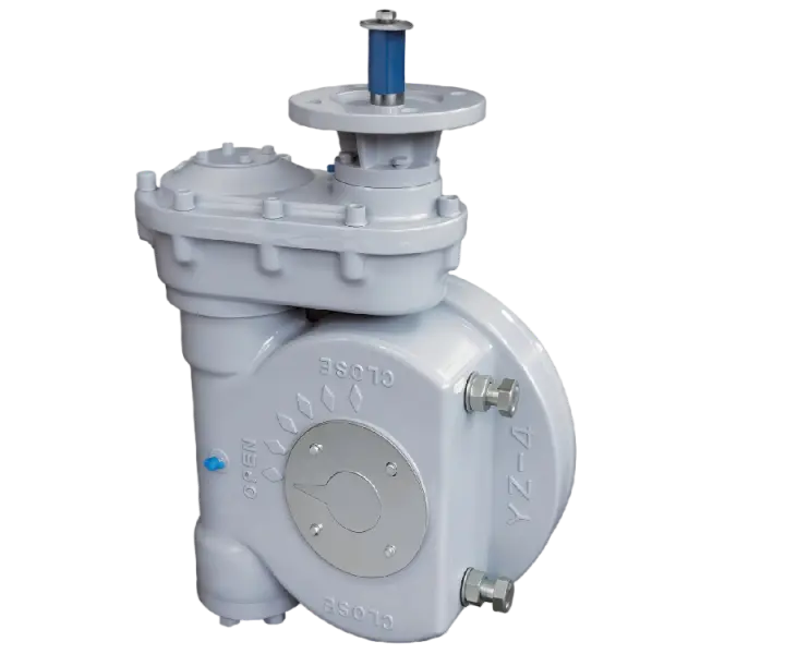
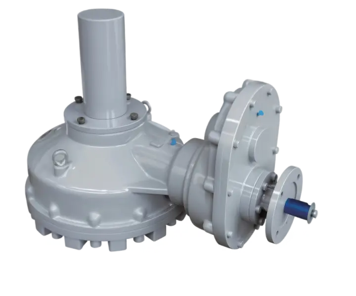
The output assembly is where the two families stop sharing parts. A part-turn unit ends in an output shaft or hub that connects to the stem and swings between two stops. A multi-turn unit ends in a stem nut or a stem coupling, supported by bearings that take the axial load. The housing around them can look similar.
On a part-turn unit, the output may be a keyed shaft, a square or a splined hub. The connection has to match the valve stem exactly, because a keyed output cannot drive a square stem, and a shallow keyway will not transmit the rated torque. The stops sit beside the output and are set at the factory or on the valve.
On a multi-turn unit, the stem nut is machined to the stem thread, often a trapezoidal thread. The output assembly holds the nut axially and lets it turn, so the threaded stem travels through it. That is the point where torque becomes linear motion, and it is also the point where stem thrust enters the gearbox.
Travel Stops and Position Indication
Part-turn gearboxes use adjustable mechanical stops to set the open and closed positions. The stops limit travel and prevent the disc or plug from turning past the designed position. The valve seat, or the actuator torque switch, should absorb the seating load. Multi-turn gearboxes do not use a 90-degree stop. Their travel is counted in stem revolutions and limited at the valve or by the actuator.
Mechanical stops and limit switches
The two devices do different jobs. A limit switch reports position to the control system, while a mechanical stop prevents movement beyond a point. A part-turn gearbox needs the stop even when the actuator has limit switches, because a failed switch must not allow over-travel. On a multi-turn valve, the closed position is set by the valve seat. A motorized gearbox ends the stroke through its limit or torque switch, and a manual gearbox is stopped by the operator at the seat.
Position indication follows the same logic. A part-turn unit shows an angle on a dial; a multi-turn unit shows a revolution count or a stem position. The indicator helps the operator confirm the stroke, but it is not the device that limits it.
Thrust: The Load a Multi-Turn Gearbox Must Carry
A multi-turn gearbox sits in two load paths at once. Torque turns the stem, and thrust pushes or pulls it. Closing a gate valve drives the stem down against the seat; opening pulls it back. The stem nut, its bearing and the housing must carry that axial force while the stem turns.
A part-turn gearbox is loaded mainly in torque. The stem rotates but does not translate, so there is no stem stroke to react. That is why a multi-turn unit is specified with a thrust limit as well as a torque limit, while a part-turn unit is specified mainly by torque.
Thrust does not disappear when the gearbox is motorized. The thrust is carried by the gearbox thrust bearing and the valve mounting. An actuator thrust base applies only where the actuator drives the stem directly. If the output assembly is not built for it, the stem can move under load or the bearing can fail. Ask for the thrust figure early, before the housing size is fixed.
Gear Types Follow the Structure
Part-turn units are mostly worm-driven. A worm stage with a self-locking lead angle gives a large reduction in one compact housing and holds the valve position when the handwheel is released. Multi-turn units often use a bevel stage, sometimes followed by a spur stage, because the stem thread already converts rotation into linear travel, so a lower gearbox ratio is often enough.
Why Bevel Multi-Turn Ratios Are Lower
A gate valve may need 20 stem turns for a full stroke. If a 60:1 gearbox were fitted, the operator would make 1,200 handwheel turns. A bevel unit at 3:1 or 5:1 keeps the stroke within a practical number of turns while still raising torque. The lower ratio matches the motion the stem already provides. Worm multi-turn units are the special case. They mainly serve three-way ball valves and other valves that rotate past 90 degrees, where a higher worm ratio keeps manual torque within reach over the longer travel.
| Series | Structure | Gear type | Output torque (Nm) | Ratio range | Valve-side flange |
|---|---|---|---|---|---|
| MY | Part-turn or multi-turn | Worm | 300–8,500 | 24:1–68:1 | ISO 5211 (part-turn); ISO 5210 (multi-turn) |
| MY-1S | Part-turn or multi-turn | Worm with spur stage | 1,000–170,000 | 72:1–5280:1 | ISO 5211 (part-turn); ISO 5210 (multi-turn) |
| MY-V | Multi-turn | Bevel | 216–7,250 | 2.3:1–7.1:1 | ISO 5210 |
| MY-V-SD | Multi-turn, electric input | Bevel with spur stage | 450–100,000 | 5:1–335:1 | ISO 5210 |
| YZ-S | Part-turn | Worm with spur stage | 1,300–850,000 | 78:1–19320:1 | ISO 5211 |
The table maps structure, not a performance ranking. A larger torque figure does not make a multi-turn unit suitable for a ball valve, and a compact part-turn unit is not a substitute for a gate valve operator. Compare within the correct family.
Handwheel Turns and Operating Effort
Manual operation is limited by turns and rim force. The ratio fixes the number of turns, while the handwheel diameter and input torque fix the force at the rim. Check both before accepting a manual gearbox, especially on a valve that is operated often.
Input turns = gear ratio × output turns
A 60:1 part-turn unit needs 15 handwheel turns for a 90-degree stroke, because a quarter turn is 0.25 output turns. A 3.1:1 multi-turn unit with a 20-turn stem stroke needs 62 input turns. The second gearbox takes fewer input turns per output revolution but needs many output revolutions to complete the stroke.
The examples are illustrative only. They use ratios from the YOYAGE range but do not represent a specific valve or a published operating time.
F = Tin / r
F is the force at the wheel rim in newtons, Tin is the torque at the gearbox input in newton-metres, and r is the handwheel radius in metres. Use half the wheel diameter for r, because the formula works on the lever arm, not on the wheel size.
At 60 Nm input and a 0.30 m handwheel radius, the rim force is 200 N. A smaller handwheel raises that force; a larger one lowers it. A higher ratio lowers the input torque but adds turns. The two adjustments trade against each other, and neither one alone makes a large valve easy to operate by hand.
Which Actuator Fits Each Structure
Both gearbox families are normally driven by a multi-turn electric actuator. The actuator makes the input turns the stroke needs: 15 turns for a 60:1 part-turn unit, dozens for a gate valve gearbox. Its limit switches are set to that turn count, and the gearbox stop or the valve seat ends the travel.
A part-turn, or quarter-turn, actuator is a different product. Its output turns 90, 180 or 270 degrees inside its own housing and mounts straight onto a quarter-turn valve on an ISO 5211 flange. It cannot supply 15 input turns, so it does not drive a reducing gearbox; it drives the valve directly.
A handwheel or chainwheel behaves like the multi-turn actuator. The operator supplies the revolutions, and the gearbox stop or the valve ends the stroke. The limits are the turn count and the rim force from the previous section.
Input Flange and the Order of Selection
The actuator mounts to the gearbox input, not to the valve. The gearbox input flange follows ISO 5210 or JB2920-81, F10 to F40 in the YOYAGE range, and the actuator output flange must match that size. Send the actuator model or its flange drawing with the order. YOYAGE marks an electric actuator input with a D in the model code, as in the MY-D part-turn unit or the MY-V-SD multi-turn gearbox.
Choose the gearbox and the actuator as one pair. The valve fixes the output motion and the stops, the required torque fixes the ratio, and the ratio fixes the input turns and the input torque the actuator has to supply. Check the turn range, torque and flange on both sides before either is ordered; each can match its own data sheet and still fail to mate with the other.
Five Checks Before You Choose
The valve type comes first; the catalog comes later. Five checks turn a valve description into one gearbox family and one model.
- Confirm the valve type and stem motion. Quarter-turn for butterfly, ball and plug; multi-turn for gate and globe. Confirm whether the stem rises or turns in place.
- Confirm the output revolutions and stem travel. Count the stem turns for a full stroke, and record the stem thread or bore.
- Confirm torque and thrust. Add the safety factor to the valve torque, and add the stem thrust for a multi-turn valve.
- Confirm the drive and input. Manual, electric actuator input or pneumatic declutchable, plus the actuator flange data.
- Confirm the connection and environment. Valve-side flange, stem connection, protection rating, coating class and mounting position.
A gearbox can match the torque and still run out of stem travel or hit a stop early. Use the valve gearbox selection guide for the full method, and check the test capabilities under quality control.
Send the valve type, stem motion and torque. YOYAGE will confirm the family and the model.
Five Assumptions to Check Before Ordering
- A multi-turn gearbox does not always have a stem nut. A non-rising stem needs a coupling that turns the stem, and the stem type decides the output.
- A higher ratio adds turns and reduces input torque. On a multi-turn stroke, an excessive ratio can make manual operation impractical.
- Thrust follows the stem into the gearbox. On a rising stem, the seat load passes through the stem nut, its thrust bearing and the output housing, so the gearbox needs a thrust rating as well as a torque rating.
- A limit switch reports position. Only the mechanical stop prevents over-travel when the switch fails or is set wrong.
- The maximum torque and thrust ratings are capacities, not the actual output torque or stem thrust. A manual gearbox delivers the handwheel input torque multiplied by the ratio and the gear efficiency, while the catalog figure only states what the gears, bearings and housing can carry. If the valve needs more output torque, or the rim force is too high, fit a larger handwheel or a higher ratio.
The structural definitions sit alongside the valve gearbox fundamentals and the product range.
Frequently Asked Questions
Yes. Part-turn and quarter-turn describe the same 90-degree output, and the terms are used interchangeably for gearboxes on butterfly, ball and plug valves. The gearbox turns the valve stem through a quarter revolution between the open and closed positions. The mechanical stops inside the gearbox limit that travel, so the valve cannot turn past either end position.
No. A part-turn gearbox stops after 90 degrees and has no stem nut for a threaded stem. A gate valve needs many stem revolutions, and the stem may move axially against the seat. Using a part-turn unit would leave the gate partly stroked and could damage the stem connection. The valve type decides the gearbox family.
Not unless it is built with quarter-turn travel stops. A multi-turn unit without those stops can drive a ball valve past its designed position. The ball, disc or plug needs a defined 90-degree travel, and the gearbox must provide mechanical stops for that motion. Torque alone does not make a multi-turn unit suitable for a quarter-turn valve.
The input turns equal the gear ratio divided by four, because a quarter turn is one quarter of an output revolution. A 24:1 gearbox needs six handwheel turns; a 60:1 unit needs fifteen. The ratio also sets the input torque, so a higher ratio gives more output torque and more turns for the same stroke.
A multi-turn valve stem moves axially as it turns, and the seat load is carried through the stem. Closing a gate or globe valve pushes the stem against the seat, and opening pulls it back. The gearbox output, its stem nut and its thrust bearing must carry that force. Torque capacity alone does not cover this load.
A worm gearbox is self-locking when the worm lead angle is below the friction angle, so the valve holds position when the handwheel is released. Bevel and spur gearboxes are generally not self-locking. On a motorized multi-turn unit, the actuator brake or control system holds the position. Confirm the requirement when flow or vibration can push the valve back.
Start with the valve type and stem motion, then give the required output torque with safety factor, the stem dimensions, and the thrust for a multi-turn valve. Add the drive type, mounting flange, protection rating, coating and mounting position. The valve motion chooses the family; the data chooses the model within it.
Standards and References
- ISO 5211:2026 Industrial valves — Part-turn actuator attachments
- ISO 5210:2026 Industrial valves — Multi-turn actuator attachments
- MSS SP-101 Part-Turn Valve Actuator Attachment — Flange and Driving Component Dimensions and Performance Characteristics
- IEC 60529:2013 Degrees of protection provided by enclosures (IP Code)
- ISO 12944-2:2017 Corrosion protection of steel structures by protective paint systems — Classification of environments