
What Is a Valve Gearbox?
A valve gearbox is a gear-reduction device mounted between a valve stem and a handwheel, chainwheel or actuator. It converts a low input torque at high speed into a high output torque at low speed, so one operator can seat a large valve or a smaller actuator can drive it.
Water, oil and gas, power generation and chemical plants use it wherever a valve is too large or too stiff to turn by hand alone, and wherever the available actuator torque is below what the valve needs.
Gearbox, gear operator, and actuator: the terms in practice
The three terms are often mixed. A valve gearbox is the gear set in its housing. A valve gear operator is the same gearbox fitted with a handwheel or chainwheel and ready to mount on a valve. A valve actuator is a powered device, electric or pneumatic, that supplies torque itself.
Where it sits in the valve control chain
The gearbox occupies one position in a short mechanical chain, and everything upstream and downstream of it has to match.
- Input side: a handwheel, a chainwheel, or the mounting flange of an electric or pneumatic actuator.
- Gear stage: worm, bevel or spur gearing that reduces speed and raises torque.
- Output side: an output shaft or hub on part-turn units, a stem nut on multi-turn units.
- Valve side: the valve stem, the mounting flange and the valve body.
The gearbox therefore multiplies torque, reduces operating speed, holds position where the gear train is self-locking, and provides a standard interface between the drive and the valve. See the YOYAGE valve gearbox range for the series covered, or the definition of gear ratio in the selection guide.
How a Valve Gearbox Multiplies Torque
A valve gearbox multiplies torque by reducing speed. Output torque is the input torque multiplied by the gear ratio and by the transmission efficiency of the gear train.
Tout = Tin × i × η
Efficiency is never 100%. Spur and bevel stages lose less energy than a worm stage, and efficiency falls at very high ratios, heavy loads and poor lubrication. Ratio alone does not fix the model.
Worked example: 24:1 on a manual valve
Suppose one operator applies 50 Nm at the handwheel rim and the gearbox ratio is 24:1. With an assumed efficiency of 0.85, the output torque is about 1,020 Nm, and the handwheel has to turn 24 times for one turn of the valve stem.
This example is illustrative only and is not a published efficiency figure for any YOYAGE series. Actual efficiency depends on gear type, load, lubrication and temperature.
Self-locking and position holding
A worm gearbox is self-locking when the worm lead angle is below the friction angle: once the handwheel is released, the valve stays where it was set without an external brake. Units with a higher lead angle can back-drive, so confirm the requirement with the supplier.
Bevel and spur gearboxes are generally not self-locking. With an electric actuator, the actuator brake and control system hold the position; in manual service a separate holding device may be needed. Back-driving is a real concern on large valves exposed to flow-induced torque, so tell the supplier when the process can push the valve back.
Input torque and gear ratio are defined in the selection guide glossary.
Part-turn vs Multi-turn Valve Gearboxes
The first structural decision is part-turn or multi-turn, and the valve type makes it. A valve that closes on a quarter turn needs a part-turn gearbox; a valve that lifts its stem needs a multi-turn gearbox with a stem nut.
| Feature | Part-turn | Multi-turn |
|---|---|---|
| Output motion | 90° rotation, limited by mechanical stops | Several full revolutions |
| Typical valves | Butterfly, ball, plug | Gate, globe |
| Valve-side flange | ISO 5211 | ISO 5210 |
| YOYAGE torque range | 300–850,000 Nm | 216–170,000 Nm |
The two structures are not interchangeable. A part-turn gearbox cannot operate a gate valve, and a multi-turn gearbox does not provide the fixed 90° stop that a quarter-turn valve needs. Some worm series, such as the MY, are built in both configurations, but the valve interface decides which version is supplied. The part-turn vs multi-turn comparison covers thrust, travel stops, handwheel turns and actuator matching; browse part-turn valve gearboxes or multi-turn valve gearboxes for the series.
Worm, Bevel and Spur: Gear Types Compared
Inside the housing, the gear set decides the ratio range, the direction of power flow and whether the gearbox is self-locking.
| Gear type | Motion | YOYAGE ratio range | Self-locking | Typical use |
|---|---|---|---|---|
| Worm | Worm screw drives a worm wheel; input and output at 90° | 24:1–8860:1 (single worm stage) | Yes, below the friction angle | Compact part-turn units, high reduction in one stage |
| Bevel | Bevel gear pair changes the drive direction by 90° | 2.35:1–924:1 | No, generally | Multi-turn units where efficiency and layout matter |
| Spur | Parallel-shaft gears, single or multi-stage | 2.5:1–24:1 per stage; combined stages for higher torque | No | An added stage raises torque, as in the YZ-S series to 850,000 Nm |
A worm stage gives a very large reduction in one compact step and can be self-locking, at the cost of lower efficiency. A bevel pair turns the drive through 90° with high efficiency and is normally used on multi-turn units. Spur gears are usually added as a second stage, because each added stage raises output torque without making the first stage enormous.
What the model suffix means
The prefix is only a model code: MY and YZ carry no separate meaning. The suffix describes the build. S combines the standard gear unit with a spur stage, which raises both the ratio and the output torque. D adds a flange for an electric actuator, so the input becomes an electric actuator input. See the worm gearbox, bevel gearbox and spur gearbox sections of the product range.
Inside a Valve Gearbox: Key Parts
A valve gearbox looks like a casting from the outside, but its performance is set by a small number of load-bearing parts. The housing carries the reaction loads from the gear mesh and keeps the shafts aligned.
- Gear set: the worm and worm wheel, the bevel pair, or the spur gear train that carries the load.
- Housing: standard ductile iron, with WCB, CF8/CF8M and LCC/LCB/LC1 options for other service conditions.
- Seals, gaskets and lubricant: keep water and dust out and keep the lubricant in.
- Input shaft: carries the handwheel, chainwheel or actuator mounting flange.
- Output element: an output shaft or hub on part-turn units, a stem nut on multi-turn units.
- Bearings and thrust surfaces: take the radial and axial loads produced by the gear stage.
- Position indicator and travel stops: show the valve position and limit travel on part-turn units.
- Mounting flange and fasteners: connect the gearbox to the valve or actuator on ISO 5211 or ISO 5210 dimensions.
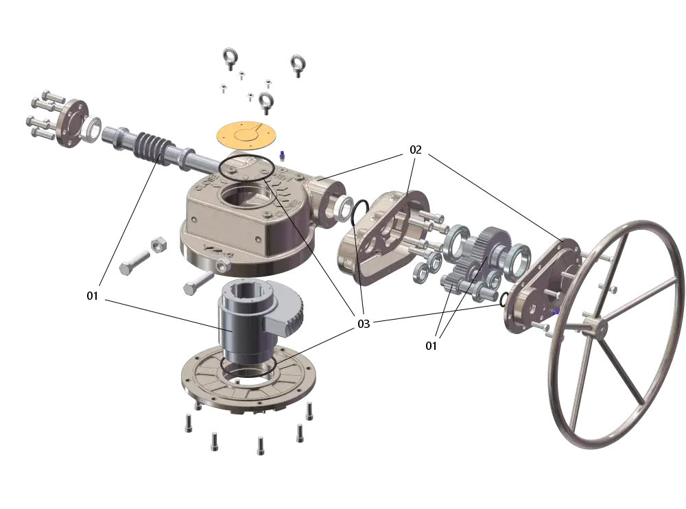
Part names differ between worm, bevel and spur designs, but the load path is the same: input shaft, gear stage, output element, valve stem. A loose flange, a damaged seal or an unlubricated bearing interrupts that path, and the valve becomes hard to operate or will not hold position. The MY worm series is an example of this layout in a manual part-turn unit.
Valve Gearbox vs Electric Actuator
A gearbox and an electric actuator solve different problems. The gearbox changes torque and speed; the actuator supplies the power to move the valve. Many installations use both in series.
| Criterion | Manual gearbox | Electric actuator | Actuator + gearbox |
|---|---|---|---|
| Power source | Operator | Electric motor | Electric motor |
| Torque source | Handwheel input × ratio × efficiency | Motor output | Motor output × gearbox ratio × efficiency |
| Position holding | Gear train, self-locking on worm types | Motor brake and control | Combined |
| Typical use | Infrequent manual operation, no power supply | Frequent or automated cycling | High torque beyond actuator rating |
When a gearbox is combined with an actuator
A gearbox is added ahead of an actuator when the valve needs more torque than the actuator can deliver. The actuator mounts on the gearbox input flange, the gearbox multiplies its torque, and the combination drives the valve stem.
YOYAGE builds these combinations with the D suffix, for example MY-D and YZ-D. The input side follows ISO 5210 or JB2920-81, depending on the actuator. See electric actuator operated gearboxes, or the MY-V-SD bevel valve gearbox for a multi-turn example.
How to Select a Valve Gearbox in Five Steps
Selection starts from the valve, not from a catalog page. Five checks turn a valve specification into one gearbox model.
- Confirm the valve type and structure. Part-turn for butterfly, ball and plug valves; multi-turn for gate and globe valves.
- Confirm the drive type. Manual handwheel or chainwheel, electric actuator input, or pneumatic declutchable.
- Confirm the required output torque. Include the safety factor, then choose the series whose maximum torque is above that figure and closest to it.
- Confirm the ratio and input size. Check the handwheel or chainwheel diameter against the effort one operator can apply; for an actuator input, check the actuator torque and flange instead.
- Confirm the connection and the environment. Stem bore or thread, ISO 5211 or ISO 5210 flange, then protection (IP65 or IP67, IP68 optional) and coating (C3 or C5).
A model can look correct on torque and still fail to mount because the stem dimensions or bolt circle were never confirmed. Check them before the drawing is released, and use the full valve gearbox selection guide for the detailed method.
Send the valve type, torque and stem data, and the YOYAGE team will confirm the model and flange.
Six Common Misunderstandings About Valve Gearboxes
Six assumptions are worth checking against a drawing.
- “A gearbox and an actuator are the same thing.” The gearbox is a transmission; the actuator is a power source. A manual gearbox needs no power supply.
- “A higher ratio is always better.” A higher ratio gives more output torque but slower operation and more handwheel turns. Match the ratio to the input effort one operator can apply, not to the largest number in the catalog.
- “One gearbox fits any valve.” Part-turn and multi-turn structures, stem connections and flange patterns all have to match the valve.
- “Torque is the only specification that matters.” Multi-turn units also carry thrust, and the stem nut has to match the stem thread or bore.
- “The IP rating also protects against corrosion.” Ingress protection and corrosion protection are separate requirements. IP65 or IP67 keeps water and dust out; C3 or C5 coating and the housing material resist the environment.
- “A gearbox needs no maintenance.” Seals, lubrication and mounting position affect long-term reliability. Follow the installation and inspection instructions rather than assuming a sealed gearbox is maintenance-free.
The materials and protection options behind these points are summarized under valve gearbox advantages.
What to Include in a Valve Gearbox RFQ
A quotation is only as good as the data behind it. Write the valve and the service conditions as checkable values, and the model can be confirmed in one pass.
- Valve type and size: butterfly, ball, plug, gate or globe, with the nominal size.
- Required output torque: including the safety factor you apply.
- Stem dimensions: thread, key or square, with bore and keyway sizes.
- Mounting flange: ISO 5211 or ISO 5210, with the bolt circle if the valve is non-standard.
- Drive type: handwheel, chainwheel, electric actuator or pneumatic declutchable, with actuator data.
- Environment: protection rating, coating, ambient temperature and mounting position.
- Quantity and destination: plus any documentation you need with the shipment.
If some values are still unknown, send what you have. The YOYAGE team reviews the application and recommends a model rather than waiting for a complete data sheet. Use the inquiry form or check the valve gearbox FAQ first.
Frequently Asked Questions
A valve gearbox is a mechanical transmission: it multiplies the torque applied at a handwheel or actuator and holds the valve position through its gear train. A valve actuator is a powered device, electric or pneumatic, that supplies the operating torque itself. A gearbox can be used alone for manual operation, or combined with an actuator when higher torque is needed.
A valve gear operator is the complete manual operating assembly: a gearbox with a handwheel or chainwheel on its input shaft, plus the mounting flange and output connection for the valve stem. The term is often used interchangeably with valve gearbox, but gear operator usually means the ready-to-mount manual unit rather than the bare gear unit.
Look at how the valve stem moves. Butterfly, ball and plug valves rotate through 90 degrees, so they use part-turn gearboxes with mechanical travel stops. Gate and globe valves lift or lower the stem over several turns, so they use multi-turn gearboxes with a stem nut. The valve type, not the torque, decides the structure.
The gear ratio is the number of input turns needed for one output turn. A 24:1 ratio means 24 handwheel turns rotate the output shaft or stem nut once. A higher ratio delivers more output torque and slower operation, while a lower ratio is faster but needs more input effort for the same valve torque.
Worm gearboxes are self-locking within their design range, so the valve keeps its position after the handwheel is released. Bevel and spur gearboxes are generally not self-locking and rely on an actuator brake or a separate holding device. Confirm the requirement whenever flow or vibration could push the valve back.
YOYAGE part-turn valve gearboxes cover 240 to 850,000 Nm, and multi-turn valve gearboxes cover 216 to 170,000 Nm. The 22 standard series include worm, bevel and spur designs in manual, electric-actuator-input and pneumatic declutchable versions. A model is chosen by matching its rated torque to the valve requirement including the safety factor.
Send the valve type and size, the required output torque including safety factor, the stem dimensions (thread, key or square), the mounting flange standard, and the drive type with handwheel or actuator data. Add the environment, meaning protection rating, coating, temperature and mounting position, plus quantity and destination.
Standards and References
- ISO 5211:2026 Industrial valves — Part-turn actuator attachments
- ISO 5210:2026 Industrial valves — Multi-turn actuator attachments
- MSS SP-101 Part-Turn Valve Actuator Attachment — Flange and Driving Component Dimensions
- IEC 60529:2013 Degrees of protection provided by enclosures (IP Code)
- ISO 12944-2:2017 Corrosion protection of steel structures by protective paint systems — Classification of environments
- ASTM A536 Standard specification for ductile iron castings